
On this page
Editorial field guide · Electrical system
Marine Diesel Electrical Basics
Most marine diesel electrical faults are found by following voltage under load, not by looking for a visibly broken wire. Start with the circuit diagram and safe isolation procedure.
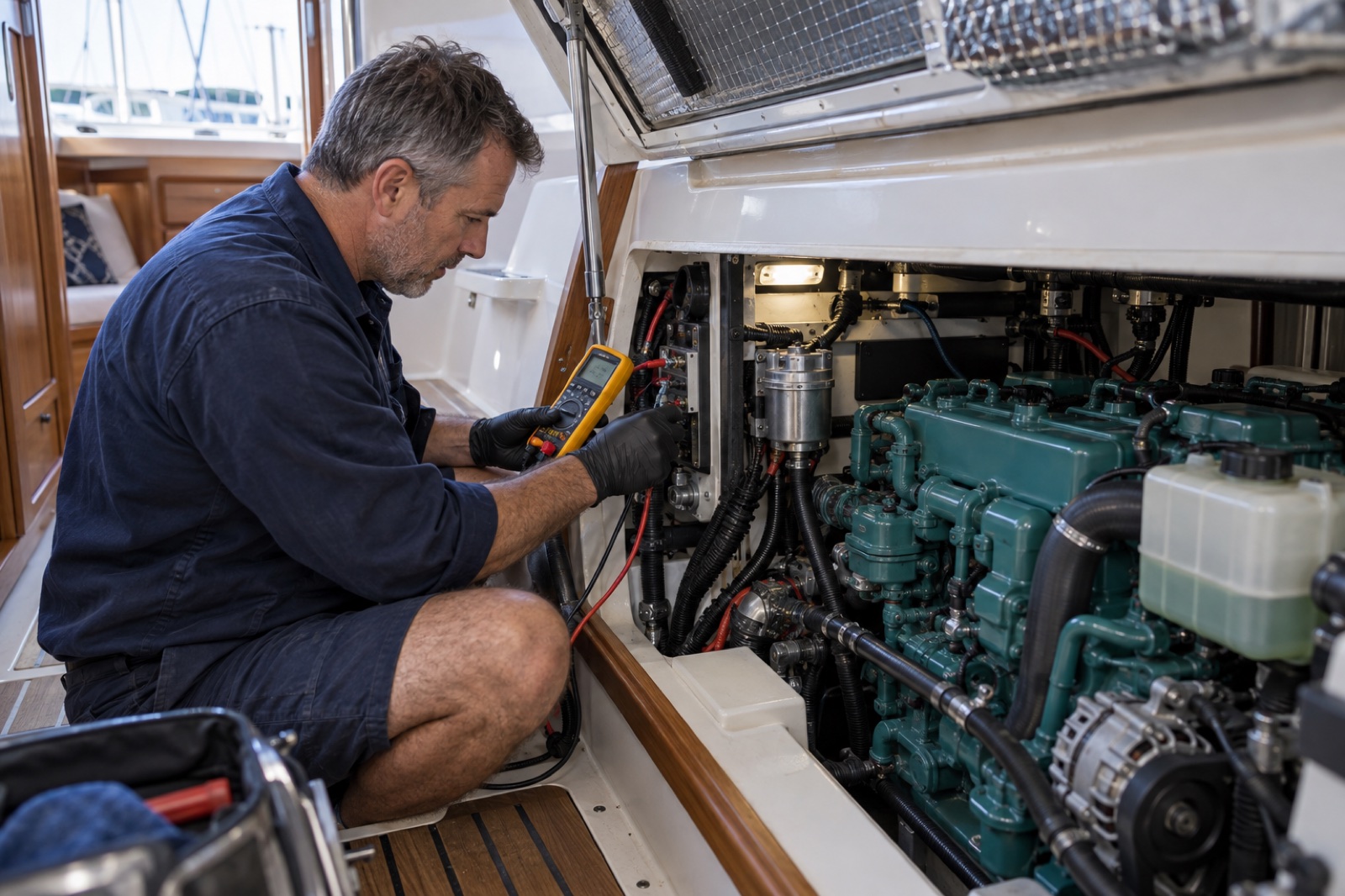
The starting circuit
The battery, isolator, cables, solenoid and starter form one high-current loop. A battery can show normal open-circuit voltage yet collapse under cranking. Measure voltage drop across positive and negative paths while the fault is present, using guarded probes and safe positioning.
Charging is a system
Alternator output depends on belt drive, regulator strategy, battery state, cable size, temperature sensing and connection quality. Verify voltage at the alternator and batteries under known load rather than assuming a dashboard number represents both.
Alarms and senders
Oil-pressure and temperature switches commonly complete a circuit to activate an alarm, but arrangements vary. The panel self-test proves only part of the circuit. Never bypass a sender or alarm as a permanent cure.
Corrosion and connections
High resistance often hides inside a crimp, isolator or engine earth strap. Cleanliness alone is not proof. Inspect heat damage and movement, then measure under load. Replace terminals with correctly sized tinned cable, sealed crimps and supported routing.
Frequently asked questions
Why do dash lights work but the starter only clicks?
Lights draw little current. A weak battery, high-resistance cable or solenoid fault may fail only under starter load.
Can an alternator be tested by removing a battery cable?
No. Disconnecting a battery while running can create damaging voltage spikes and is unsafe. Use proper electrical measurements.
What is voltage drop testing?
It measures voltage lost across a cable, switch or connection while current flows, revealing resistance that a visual inspection can miss.
Terminology can differ between manufacturers. For definitive specifications and intervals, consult the current manual for the exact engine and the relevant manufacturer or Australian authority resource.
- 1Battery bank
- 2Isolation & fuses
- 3Starter circuit
- 4Alternator
- 5Panel & alarms